Scientific Basis for Hydraulic Breaker Model Selection
Picking the right model is key to getting the best results from your gear. It also helps safeguard the main excavator and makes attachments last longer. A wrong choice can lead to poor output, high expenses, and even harm to the machine.
Core Matching Principle: Excavator Tonnage and Hydraulic Breaker Model
The weight and total load of the excavator play the biggest role in choosing a Hydraulic Breaker model. You need to stick closely to the matching rules.
- Matching Analysis: A Hydraulic Breaker that is too big or too small creates big issues. If it’s too large, it demands more impact power and speed than the excavator’s hydraulic setup can handle. This leads to overload on the main pump. The system gets too hot. Plus, constant strong forces cause early cracks in the turntable and arm parts. On the other hand, a model that is too small fails to use the excavator’s full hydraulic strength. As a result, you get low energy transfer and work speed that’s way below what you expect. From a cost standpoint, this makes the whole setup a bad deal.
- Reference Standard: Popular Hydraulic Breaker models line up with main specs. Start by making sure the excavator’s weight fits the range suggested by the maker. Then, look at the chisel size as a quick way to narrow down options.
Working Condition Adaptability Selection: Detailed Explanation of Structural Forms
Various Hydraulic Breaker designs fit certain job sites best. Choosing the proper one based on your tasks boosts output and strength.
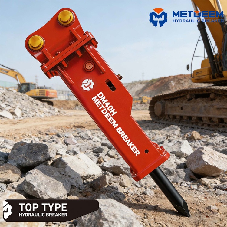
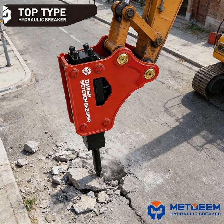
Top-Type Hydraulic Breaker
- Structure and Features: The body casing and chisel holder sit at nearly a right angle. This makes the whole unit tight and balanced, with its weight point near the excavator arm’s joint.
- Advantageous Working Conditions: This type works well in tough spots that need operation from many angles. Think of jobs with strong side forces or straight-up breaking, like tearing down old buildings or cleaning up mine sites. The setup gives better control and a broader reach for angles.
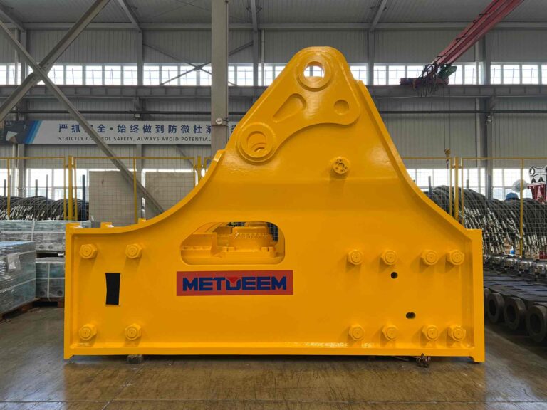
Side-Type Hydraulic Breaker
- Structure and Features: The back of the casing stretches out to form a solid triangle base. The arm setup handles mainly straight-down hits.
- Advantageous Working Conditions: It’s built for flat-ground tasks, such as digging roads or busting foundations. The sturdy build spreads out and takes in steady down-force stress, holding up longer in those scenarios.
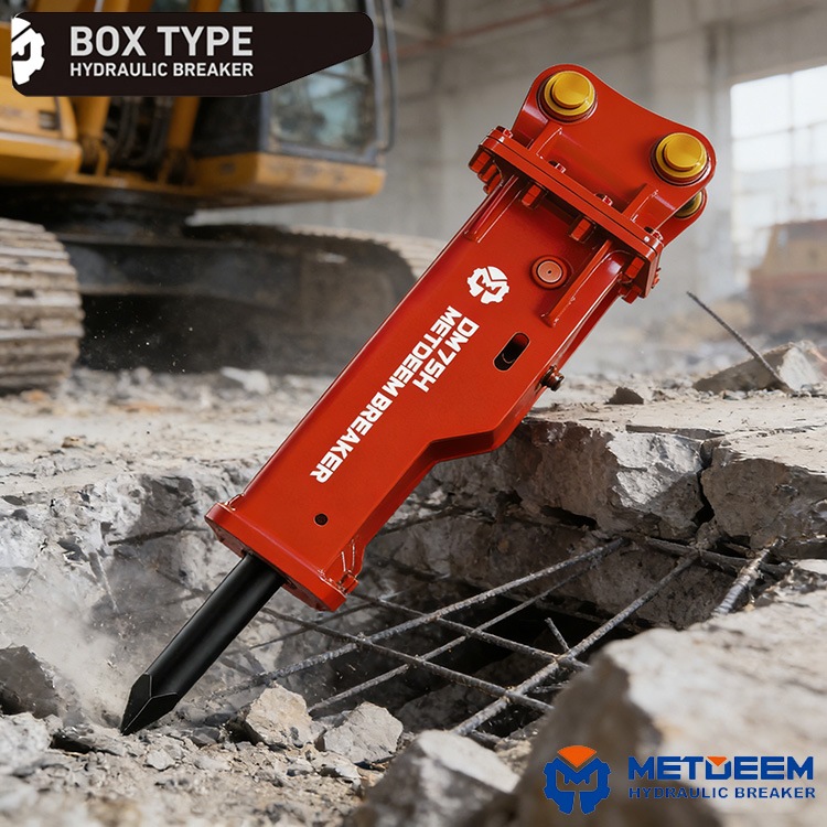
Box-Type Hydraulic Breaker
- Structure and Features: It has a noise-dampening layer inside the usual shell. Or it adds a full cover to cut down sound. This greatly lowers the noise from hits during use.
- Advantageous Working Conditions: Use it in spots with tight rules on noise, like city zones, homes nearby, tunnels, or factory interiors.
Standardized Installation Process for Hydraulic Breakers
Following set steps for setup is vital for safe and smooth work. Only trained folks should handle it.
Key Data Verification Before Installation
Get these mechanical and hydraulic details right and double-check them before starting.
- Mechanical Interface: Measure the pin hole size at the boom’s end (the chiseltip) and the space between side plates.
- Attachment Interface: Note the pin hole size on the breaker’s top mount and the ear plate thickness.
- Hydraulic Interface: Make sure the excavator has updates for a quick hydraulic coupler and lines that match the breaker’s setup.
Main Machine Mechanical Connection Procedures
- Safety Preparation and Bucket Removal: Park the excavator on solid, even ground. Drop the bucket down to let out any leftover hydraulic pressure. Then, take out the bucket pin.
- Attachment Lifting and Alignment: Bring in proper lifting gear to raise the breaker gently. Move it into place slowly. Line up the breaker’s mount holes exactly with the boom’s rod holes.
- Pin Insertion and Locking: Slide in the link pin all the way. Right away, add the lock (like a clip, nut, or plate) to stop it from slipping out from shakes. Grease the pin well for smooth action.
Hydraulic Piping Connection Specifications
Getting the hydraulic lines right is essential for the breaker to run properly.
- Port Identification: Find the inlet (labeled “IN” or “P”) and outlet (labeled “OUT” or “T”) on the breaker’s valve or cylinder.
- Correct Connection: Hook the excavator’s high-pressure line to the breaker’s “IN” port. Link the low-pressure return to the “OUT” port.
- Handling Incorrect Connections: If the breaker doesn’t respond after hookup, look for swapped lines first. Switching them fixes it. A short wrong setup rarely hurts parts inside, but don’t test with heavy loads.
Chisel Installation Procedure
- Removing the Locking Component: Spot the lock pin (often a spring type or bolt) that holds the chisel pin and take it out.
- Pulling Out the Chisel Pin: Pull the main chisel pin fully from the lower cylinder.
- Insert the chisel: Slide the chisel up into the holder from the bottom. Tug it to adjust until its side groove or hole lines up with the cylinder’s pin spot.
- Secure: Push the chisel pin back through the chisel and cylinder sides. Then, put in and tighten the lock pin to finish the hold.
Precise Adjustment and Initial Operation After Installation
Fine-tuning links the setup to steady, effective use over time, which cannot be omitted.
Nitrogen Pressure Testing and Filling
Nitrogen charge drives the breaker’s strong hits and softens shocks.
- Filling Tools: Use a special nitrogen kit for this job.
- Pressure Standard: Look at the “Rear Cylinder Nitrogen” in the table for the right amount (like 10-15KG/cm² for the DM45 model). Too little means soft hits and slow reset. Too much makes hits rough and wears parts fast.
- Safety Warning: Never swap in compressed air or oxygen for nitrogen. High heat and pressure can spark an explosion, as seen in past workshop incidents where improper gas led to serious damage.
Setting the Hydraulic System Parameters of the Main Unit
Tune the excavator’s hydraulic flow to fit the breaker’s needs. The table below lists METDEEM hydraulic breakers main figures to guide you.
| Model | Chisel Diameter (mm) | Pressure | Flow Rate | Rear Cylinder Nitrogen | Accumulator Pressure |
| DM30 | 30 | 8-12MPa | 15-20L/min | 12KG/cm³ | |
| DM35 | 35 | 10-15MPa | 15-20L/min | 12KG/cm³ | |
| DM45 | 45 | 10-15MPa | 20-40L/min | 15KG/cm³ | |
| DM53 | 53 | 10-15MPa | 25-50L/min | 15KG/cm³ | |
| DM68 | 68 | 16-18MPa | 40-70L/min | 16KG/cm³ | |
| DM75 | 75 | 16-18MPa | 60-80L/min | 16KG/cm³ | |
| DM85 | 85 | 16-18MPa | 80-100L/min | 16-18KG/cm³ | |
| DM100 | 100 | 18-22MPa | 80-100L/min | 16-18KG/cm³ | |
| DM125 | 125 | 20-24MPa | 80-100L/min | 16-18KG/cm³ | |
| DM135 | 135 | 20-24MPa | 160-200L/min | 22-25KG/cm³ | |
| DM140 | 140 | 20-24MPa | 160-200L/min | 22-25KG/cm³ | |
| DM140A | 140A | 20-24MPa | 160-200L/min | 22-25KG/cm³ | 60-65KG/cm³ |
| DM155 | 155 | 24-26MPa | 180-240L/min | 24-26KG/cm³ | 60-65KG/cm³ |
| DM165 | 165 | 24-26MPa | 180-240L/min | 24-26KG/cm³ | 60-65KG/cm³ |
| DM175 | 175 | 26-28MPa | 220-280L/min | 26-28KG/cm³ | 60-65KG/cm³ |
| DM190 | 190 | 30-32MPa | 260-300L/min | 28-32KG/cm³ | 60-65KG/cm³ |
| DM195 | 195 | 30-32MPa | 260-300L/min | 28-32KG/cm³ | 60-65KG/cm³ |
| DM200 | 200 | 30-32MPa | 260-320L/min | 30-34KG/cm³ | 60-65KG/cm³ |
| DM210 | 210 | 32-35MPa | 280-320L/min | 30-34KG/cm³ | 60-65KG/cm³ |
| DM230 | 230 | 34-36MPa | 300-330L/min | 35-37KG/cm³ | 60-65KG/cm³ |
- Flow rate adjustment: Set the flow to the “Recommended Flow Rate” range from the table. Do this via the excavator’s screen or a valve in the line. It controls how often it hits.
- Pressure Adjustment: Find the relief valve for the breaker line in the excavator’s system. Dial it to the “Working Pressure” value in the table. This sets the power per hit.
Initial Operation: Lubrication, Bleeding, and Break-in
- Critical Lubrication: Before firing up, pump plenty of grease into the chisel holder via the nipple.
- Key Operation: While adding grease, push the chisel into the cylinder. This squeezes the dust seal and forces lube into the inner track. It stops extra grease from gumming up the piston area.
- System Bleeding: Fire up the excavator. Hold the chisel straight down to the ground. Tap the foot control or switch for 2-3 seconds, then let go. Do this 5-10 times with breaks in between. Over time, this pushes out air from the lines until the hits sound sharp and steady.
- Break-in Operation: Once air is gone, start regular work. For the first half hour, go easy on the breaks. Don’t hammer full tilt for long stretches. This lets parts settle, lube up, and avoid early wear.
Daily and Periodic Maintenance Points
- Pre-operation inspection: Look over pins and bolts for wear, scan lines for oil drips, test nitrogen weekly, check chisel sharpness, and top up lube as needed.
- Operating procedures: Never let the chisel hit empty air; don’t pound one tough spot over 30 seconds straight; skip using it as a lever.
- Long-term storage: Clean it fully, then push the chisel all the way in. Apply anti-rust paint on the exposed metal and keep it dry.
FAQ
Q: What is the most direct consequence of a breaker hammer model not matching the excavator?
A: An oversized model will severely damage the excavator’s structural components and hydraulic system; an undersized model will result in extremely low work efficiency and poor economy.
Q: Will the breaker hammer work if the hydraulic lines are connected backwards?
A: It won’t work, but it usually won’t cause immediate mechanical damage. Simply replacing the oil line will restore normal operation.
Q: How often should the nitrogen pressure be checked?
A: It is recommended to check and adjust it at least once a week, as nitrogen will naturally leak over time and with temperature changes.
Q: Why should the chisel be pressed in when adding grease?
A: This is to allow the dust seal to contract, ensuring that the grease is injected into the internal slideway rather than squeezed out, and also preventing excess grease from entering the piston impact chamber and damaging the oil seal.
Q: Why should a newly installed hydraulic breaker be tapped several times first?
A: This is to remove air from the hydraulic lines and the breaker cylinder, preventing weak impact, excessive oil temperature, or cavitation damage to internal components caused by air ingress.